Aircraft brakes operate under extreme stress and varied conditions. They are susceptible to malfunction and damage. On review of the OMS reports we have seen brakes as a contributing factor that has led to various incident and accident such as Runway loss of control (RLOC). The below article show and identifies parts and systems that need to be serviced regularly.
Independent Master Cylinders
In general, small, light aircraft and aircraft without hydraulic systems use independent braking systems. An independent brake system is not connected in any way to the aircraft hydraulic system. Master cylinders are used to develop the necessary hydraulic pressure to operate the brakes. This is similar to the brake system of an automobile.
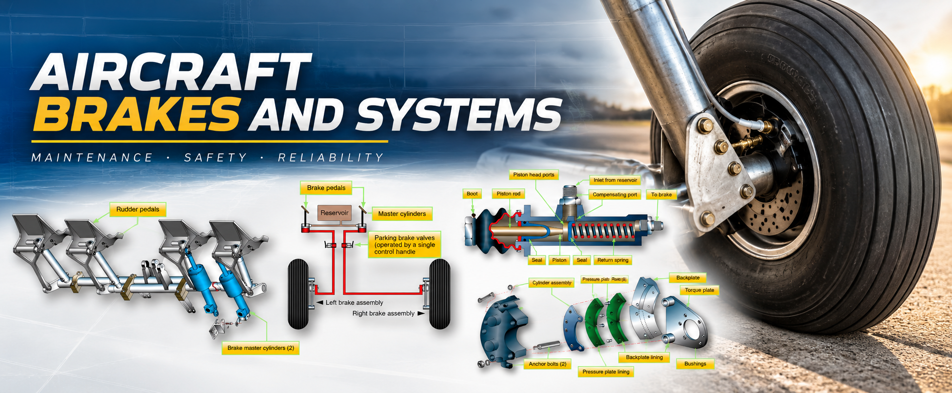
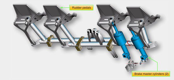
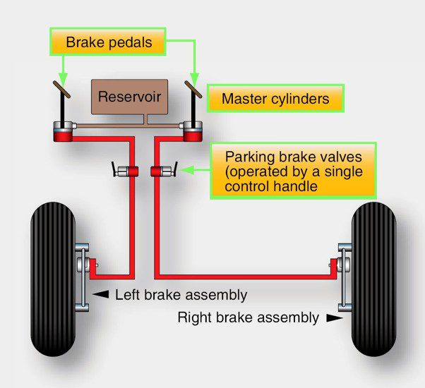
In most brake actuating systems, the pilot pushes on the tops of the rudder pedals to apply the brakes. A master cylinder for each brake is mechanically connected to the corresponding rudder pedal (i.e., right main brake to the right rudder pedal, left main brake to the left rudder pedal). [Figure 15] When the pedal is depressed, a piston inside a sealed fluid-filled chamber in the master cylinder forces hydraulic fluid through a line to the piston(s) in the brake assembly. The brake piston(s) push the brake linings against the brake rotor to create the friction that slows the wheel rotation. Pressure is increased throughout the entire brake systems and against the rotor as the pedal is pushed harder.
Many master cylinders have built-in reservoirs for the brake hydraulic fluid. Others have a single remote reservoir that services both of the aircraft’s two master cylinders. [Figure 16] A few light aircraft with nose wheel steering have only one master cylinder that actuates both main wheel brakes. This is possible because steering the aircraft during taxi does not require differential braking. Regardless of the set-up, it is the master cylinder that builds up the pressure required for braking.
A master cylinder used with a remote reservoir is illustrated in [Figure 2]. This particular model is a Goodyear master cylinder. The cylinder is always filled with air-free, contaminant-free hydraulic fluid as is the reservoir and the line that connects the two together. When the top of the rudder pedal is depressed, the piston arm is mechanically moved forward into the master cylinder. It pushes the piston against the fluid, which is forced through the line to the brake. When pedal pressure is released, the return springs in the brake assembly retract the brake pistons back into the brake housing. The hydraulic fluid behind the pistons is displaced and must return to the master cylinder. As it does, a return spring in the master cylinder move the piston, piston rod and rudder pedal back to the original position (brake off, pedal not depressed). The fluid behind the master cylinder piston flows back into the reservoir. The brake is ready to be applied again
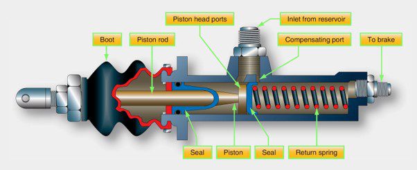
Hydraulic fluid expands as temperature increases. Trapped fluid can cause a brake to drag against the rotor(s). Leaks may also result. When the brakes are not applied, fluid must be allowed to expand safely without causing these issues. A compensating port is included in most master cylinders to facilitate this.
In the master cylinder in Figure 3, this port is opened when the piston is fully retracted. Fluid in the brake system is allowed to expand into the reservoir, which has the capacity to accept the extra fluid volume. The typical reservoir is also vented to the atmosphere to provide positive pressure on the fluid.
The forward side of the piston head contains a seal that closes off the compensating port when the brakes are applied so that pressure can build. The seal is only effective in the forward direction. When the piston is returning, or is fully retracted to the off position, fluid behind the piston is free to flow through piston head ports to replenish any fluid that may be lost downstream of the master cylinder. The aft end of the master cylinder contains a seal that prevents leakage at all times. A rubber boot fits over the piston rod and the aft end of the master cylinder to keep out dust.
A parking brake for this remote reservoir master cylinder brake system is a ratcheting mechanical device between the master cylinder and the rudder pedals. With the brakes applied, the ratchet is engaged by pulling the parking brake handle. To release the brakes, the rudder pedals are depressed further allowing the ratchet to disengage. With the parking brake set, any expansion of hydraulic fluid due to temperature is relieved by a spring in the mechanical linkage.
A common requirement of all braking systems is for there to be no air mixed in with the hydraulic fluid. Since air is compressible and hydraulic fluid essentially is not, any air under pressure when the brakes are applied causes spongy brakes. The pedals do not feel firm when pushed down due to the air compressing. Brake systems must be bled to remove all air from the system. Instructions for bleeding the brakes are in the manufacturer’s maintenance information. Brake systems equipped with Goodyear master cylinders must be bled from the top down to ensure any air trapped behind the master cylinder piston is removed.
An alternative common arrangement of independent braking systems incorporates two master cylinders, each with its own integral fluid reservoir. Except for the reservoir location, the brake system is basically the same as just described. The master cylinders are mechanically linked to the rudder pedals as before. Depressing the top of a pedal causes the piston rod to push the piston into the cylinder forcing the fluid out to the brake assembly. The piston rod rides in a compensator sleeve and contains an O-ring that seals the rod to the piston when the rod is moved forward. This blocks the compensating ports. When released, a spring returns the piston to its original position which refills the reservoir as it returns. The rod end seal retracts away from the piston head allowing a free flow of fluid from the cylinder through the compensating ports in the piston to the reservoir.
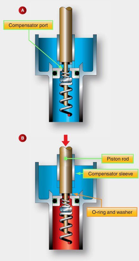
Shown above [Figure 4] is a common master cylinder with built-in reservoir is shown. Illustration A depicts the master cylinder when the brakes are off. The compensating port is open to allow fluid to expand into the reservoir should temperature increase. In B, the brakes are applied. The piston rod-end seal covers the compensating port as it contacts the piston head.
Cleveland Brakes. Common amongst RAAus registered aircraft.
The popular Cleveland brake uniquely features the ability to change the brake linings without jacking the aircraft or removing the wheel. On these assemblies, the torque plate is bolted to the strut while the remainder of the brake is assembled on the anchor bolts. The disc rides between the pressure plate and back plate. Linings are riveted to both plates. By unbolting the cylinder housing from the backplate, the backplate is freed to drop away from the torque plate. The remainder of the assembly is pulled away, and the pressure plate slides off of the torque bolts.
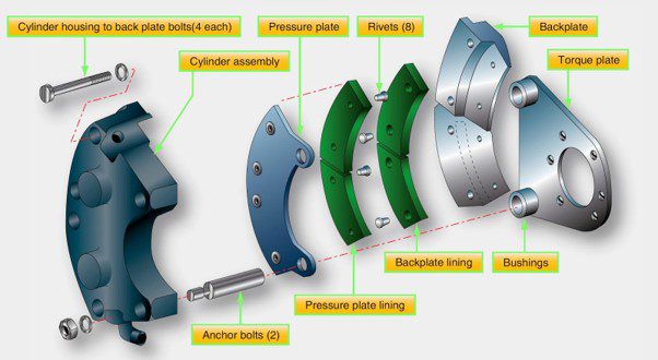
A Cleveland brake disassembles once the four bolts holding the cylinder to the backplate are removed while the aircraft wheel remains in place. The pressure plate slides off the anchor bolts and linings can be replaced by riveting on the pressure plate and back plate
The rivets that hold the linings on the pressure plate and back plate are removed with a knockout punch. After a thorough inspection, new linings are riveted to the pressure plate and backplate using a rivet clinching tool [Figure 46] Kits are sold that supply everything needed to perform the operation. The brake is reassembled in the reverse order. Be certain to include any shims if required.
The bolts holding the backplate to the cylinder assembly must be torqued according to manufacturer specifications and safetied. The manufacturer’s data also provides a burn in procedure. The aircraft is taxied at a specified speed, and the brakes are smoothly applied. After a cooling period, the process is repeated, thus preparing the linings for service.
Chattering or Squealing
Brakes may chatter or squeal when the linings do not ride smoothly and evenly along the disc. A warped disc(s) in a multiple brake disc stack produces a condition wherein the brake is actually applied and removed many times per minute. This causes chattering and, at high frequency, it causes squealing. Any misalignment of the disc stack out of parallel causes the same phenomenon. Discs that have been overheated may have damage to the surface layer of the disc. Some of this mix may be transferred to the adjacent disc resulting in uneven disc surfaces that also leads to chatter or squeal. In addition to the noise produced by brake chattering and squealing, vibration is caused that may lead to further damage of the brake and the landing gear system. The technician must investigate all reports of brake chattering and squealing.
Fluid Quantity and Type
As mentioned, it is imperative that the correct hydraulic fluid is used in each brake system. Seals in the brake system are designed for a particular hydraulic fluid. Deterioration and failure occurs when they are exposed to other fluids. Mineral based fluid, such as MIL-H-5606 (red oil), should never be mixed with phosphate-ester based synthetic hydraulic fluid such as Skydrol®. Contaminated brake/hydraulic systems must have all of the fluid evacuated and all seals replaced before the aircraft is released for flight.
Fluid quantity is also important. The maintainer is responsible for determining the method used to ascertain when the brake and hydraulic systems are fully serviced and for the maintenance of the fluid at this level. Consult the manufacturer’s specifications for this information.
Inspection for Leaks
Aircraft brake systems should maintain all fluid inside lines and components and should not leak. Any evidence of a leak must be investigated for its cause. It is possible that the leak is a precursor to more Significant damage that can be repaired, thus avoiding an incident or accident.
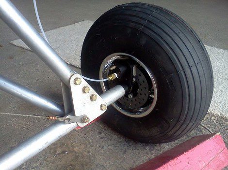
The cause of all aircraft brake leaks must be investigated, repaired, and tested before releasing the aircraft for flight.
Many leaks are found at brake system fittings. While this type of leak may be fixed by tightening an obviously loose connection, the maintainer is cautioned against over-tightening fittings.
Removal of hydraulic pressure from the brake system followed by disconnection and inspection of the connectors is recommended. Over-tightening of fitting can cause damage and make the leak worse. MS flareless fitting are particularly sensitive to over-tightening.
Replace all fittings suspected of damage. Once any leak is repaired, the brake system must be re-pressurized and tested for function as well as to ensure the leak no longer exists. Occasionally, a brake housing may seep fluid through the housing body. Consult the manufacturer’s maintenance manual for limits, and remove any brake assembly that seeps excessively.
Proper Bolt Torque
The stress experience by the landing gear and brake system requires that all bolts are properly torqued. Bolts used to attach the brakes to the strut typically have the required torque specified in the manufacturer’s maintenance manual. Check for torque specifications that may exist for any landing gear and brake bolts, and ensure they are properly tightened. Whenever applying torque to a bolt on an aircraft, use of a calibrated torque wrench is required.
Off Aircraft Brake Servicing and Maintenance
Certain servicing and maintenance of an aircraft brake assembly is performed while it has been removed from the aircraft. A close inspection of the assembly and its many parts should be performed at this time. Some of the inspection items on a typical assembly follow.
Bolt and Threaded Connections
All bolts and threaded connections are inspected. They should be in good condition without signs of wear. Self-locking nuts should still retain their locking feature. The hardware should be what is specified in the brake manufacturer’s parts manual. Many aircraft brake bolts, for example, are not standard hardware and may be of closer tolerance or made of a different material. The demands of the high stress environment in which the brakes perform may cause brake failure if improper substitute hardware is used. Be sure to check the condition of all threads and O-ring seating areas machined into the housing. The fittings threaded into the housing must also be checked for condition.
Discs
Brake discs must be inspected for condition. Both rotating and stationary discs in a multiple disc brake can wear. Uneven wear can be an indication that the automatic adjusters may not be pulling the pressure plate back far enough to relieve all pressure on the disc stack.
Stationary discs are inspected for cracks. Cracks usually extend from the relief slots, if so equipped. On multiple disc brakes, the slots that key the disc to the torque tube must also be inspected for wear and widening. The discs should engage the torque tube without binding. The maximum width of the slots is given in the maintenance manual. Cracks or excessive key slot wear are grounds for rejection. Brake wear pads or linings must also be inspected for wear while the brake assembly is removed from the aircraft. Signs of uneven wear should be investigated and the problem corrected. The pads may be replaced if worn beyond limits as long as the stationary disc upon which they mount passes inspection. Follow the manufacturer’s procedures for inspections and for pad replacement.
Rotating discs must be similarly inspected. The general condition of the disc must be observed. Glazing can occur when a disc or part of a disc is overheated. It causes brake squeal and chatter. It is possible to resurface a glazed disc if the manufacturer allows it. Rotating discs must also be inspected in the drive key slot or drive tang area for wear and deformation. Little damage is allowed before replacement is required.
The pressure plate and back plate on multiple disc brakes must be inspected for freedom of movement, cracks, general condition, and warping. New linings may be riveted to the plates if the old linings are worn and the condition of the plate is good. Note that replacing brake pads and linings by riveting may require specific tools and technique as described in the maintenance manual to ensure secure attachment. Minor warping can be straightened on some brake assemblies.
Overheating
While aircraft brakes slow the aircraft by changing kinetic energy into heat energy, overheating of the brakes is not desirable. Excessive heat can damage and distort brake parts weakening them to the point of failure. Protocol for brake usage is designed to prevent overheating.
When a brake shows signs of overheating, it must be removed from the aircraft and inspected for damage. When an aircraft is involved in an aborted takeoff, the brakes must be removed and inspected to ensure they withstood this high level of use.
The typical post-overheat brake inspection involves removal of the brake from the aircraft and disassembly of the brakes. All of the seals must be replaced. The brake housing must be checked for cracks, warping, and hardness per the maintenance manual. Any weakness or loss of heat treatment could cause the brake to fail under high-pressure braking. The brake discs must also be inspected. They must not be warped, and the surface treatment must not be damaged or transferred to an adjacent disc. Once reassembled, the brake should be bench tested for leaks and pressure tested for operation before being installed on the aircraft.
Dragging
Brake drag is a condition caused by the linings not retracting from the brake disc when the brakes are no longer being applied. It can be caused by several different factors. Brakes that drag are essentially partially on at all times. This can cause excessive lining wear and overheating leading to damage to the disc(s).
A brake may drag when the return mechanism is not functioning properly. This could be due to a weak return spring, the return pin slipping in the auto adjuster pin grip, or similar malfunction. Inspect the auto adjuster(s) and return units on the brake when dragging is reported. An overheated brake that has warped the disc also causes brake drag. Remove the brake and perform a complete inspection as discussed in the previous section. Air in the brake fluid line can also cause brake drag. Heat causes the air to expand, which pushes the brake linings against the disc prematurely. If no damage has been caused when reported, bleed the brakes to remove the air from the system to eliminate the drag.
At all times, the technician should perform inspections to ensure the proper parts are used in the brake assembly. Improper parts, especially in the retraction/adjuster assemblies, can cause the brakes to drag.