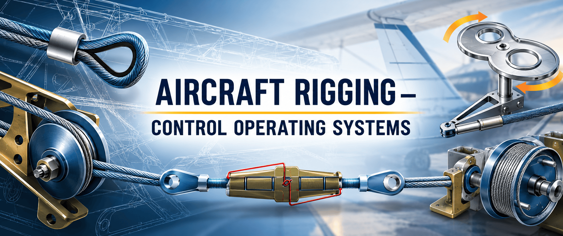
Aircraft control operating systems play an essential role in ensuring the safe and reliable operation of recreational aircraft. From control cables and pulleys to turnbuckles, push rods and torque tubes, each component must be correctly installed, adjusted and inspected.
Recreational Aviation Australia has previously identified a number of cable-related issues, reinforcing the importance of regular inspection and maintenance.
Members are reminded to follow the aircraft manufacturer’s maintenance and inspection schedule. Where applicable to amateur-built aircraft, FAA Advisory Circular AC 43.13-1B, Acceptable Methods, Techniques, and Practices – Aircraft Inspection and Repair, provides additional technical guidance.
Originally published in SportPilot (2018) by Daz Barnfield, National Technical Manager.
Understanding Aircraft Control Cables
Cable Materials and Construction
Aircraft control cables are generally manufactured from carbon steel or corrosion-resistant stainless steel. Some manufacturers also use nylon-coated cables, which provide additional protection against friction, dirt, grit and vibration.
The basic component of a cable is a wire. Individual wires are formed into strands, which are then laid around a centre strand to create the completed cable.
The construction of the cable determines its flexibility, strength and suitability for different aircraft control applications.
Cable Designations
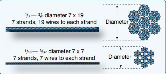
The two common cable configurations are:
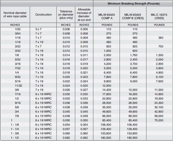
- 7 × 19 cable: Seven strands containing 19 wires each. Highly flexible and commonly used in primary flight control systems and areas where cables pass over pulleys.
- 7 × 7 cable: Seven strands containing seven wires each. Medium flexibility and commonly used in trim tab controls, engine controls and indicator systems.
Cable Terminations and Fittings
Types of Cable Terminations
Aircraft control cables require suitable end fittings or terminations to connect them to the aircraft’s control system. Common methods include woven splices, Nicopress sleeves and swage-type terminals.
Woven Splices
A traditional hand-woven five-tuck splice, generally found on some antique aircraft. This method is time-consuming and produces approximately 75% of the original cable strength.
Nicopress Process
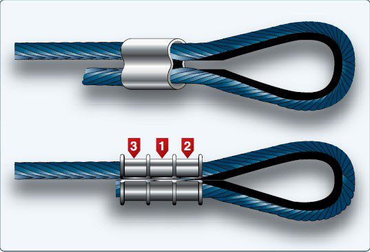
The Nicopress process uses copper sleeves to secure cable loops around a thimble. When correctly installed using the specified tools and procedures, this method can achieve the full rated strength of the cable.
It is essential that the manufacturer’s instructions, tooling and specifications are followed precisely.
Swage-Type Terminals
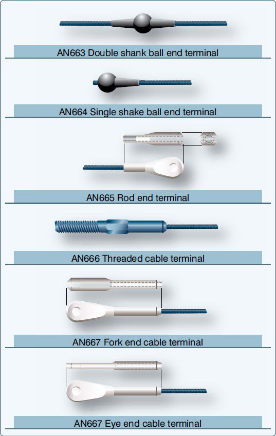
Swage terminals are manufactured to recognised aviation standards and provide a secure mechanical connection between the cable and its attachment fitting.
Common fittings include ball ends, threaded terminals, fork ends and eye ends.
Swaging and Testing Cable Assemblies
Swaging Procedures
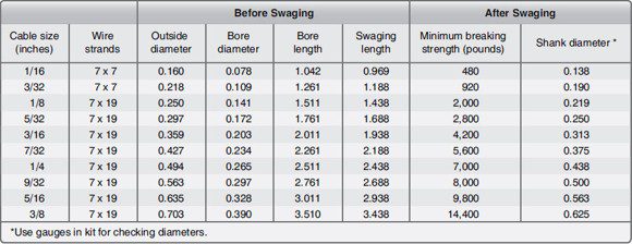
Swaging is a process used to permanently attach a terminal fitting to the end of an aircraft control cable.
Correct installation is essential to ensure the fitting develops the required strength and does not slip or fail during operation.
The basic process includes:
- Cable preparation: Cut the cable to the required length, allowing for growth during swaging. Apply the specified preservative compound and mark the insertion depth.
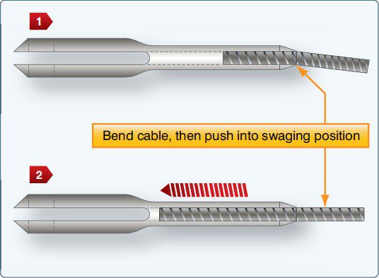
- Terminal insertion: Insert the cable into the terminal according to the manufacturer’s procedure, ensuring it reaches the correct depth.
- Swaging: Use the appropriate equipment and follow the swaging tool manufacturer’s instructions.
- Visual inspection: Check for splits, die marks, distortion, broken strands or evidence of cable movement.
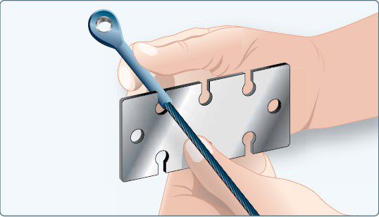
- Dimensional inspection: Use the appropriate go/no-go gauge or micrometer to confirm the terminal dimensions.
- Proof loading: Where required by the applicable procedure, test the completed cable assembly to confirm its strength before installation.
The source procedure specifies a proof load of 60% of the cable’s rated breaking strength, held for at least three minutes.
Important: Proof loading can be dangerous. Suitable protective guards and correctly rated testing equipment must be used. If appropriate equipment is unavailable, testing should be performed by a suitably equipped facility.
Cable Inspection and Common Wear Areas
Inspection and Deterioration
Aircraft control cables are exposed to environmental conditions, repeated movement and mechanical wear. Over time, these factors can lead to corrosion, broken strands, distortion and fatigue.
While broken wires may be visible during inspection, other forms of deterioration can be difficult to identify without closer examination.
Particular attention should be given to areas where cables pass through potentially corrosive environments, including battery compartments and wheel wells.
Critical Fatigue Areas
Areas requiring careful inspection include:
- Sections passing over or around pulleys.
- Locations where cables pass through fairleads.
- Areas where cables flex or rub against surrounding components.
- Sections within approximately 300mm of swaged fittings.
A traditional inspection technique involves carefully passing a cloth along the cable to identify protruding broken strands.
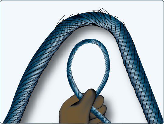
Further inspection may be necessary where internal corrosion or fatigue is suspected. The source describes loosening or removing a cable and bending it to reveal internal strand damage.
Inspection methods and cable removal must follow the applicable aircraft maintenance instructions.
Cable Guides, Pulleys and Fairleads
Cable System Installation
Control cables must be guided correctly throughout the aircraft to maintain alignment, prevent interference and allow unrestricted movement.
Pulleys
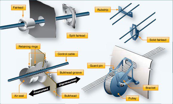
Pulleys are used to guide cables and change their direction of movement. They are supported by brackets attached to the aircraft structure, while cable guards prevent cables from slipping out of position.
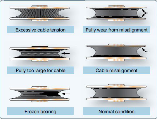
During inspection, pulleys should be checked for smooth rotation, correct alignment and unusual wear patterns.
Abnormal wear may indicate excessive cable tension, misalignment, incorrect pulley sizing or a seized bearing.
Fairleads
Fairleads guide cables through bulkheads and other structural members. They may be manufactured from non-metallic materials or suitable soft metals.
Fairleads are intended to guide cables in a straight line and should not deflect cable alignment by more than three degrees, as stated in the source material.
Pressure Seals
Pressure seals are fitted where cables or rods pass through pressure bulkheads.
These seals must allow unrestricted movement while limiting air pressure loss. Retaining rings should be inspected to ensure they remain securely positioned and cannot interfere with nearby pulleys.
Control Surface Travel and Cable Tension
Rigging and Adjustment
Aircraft flight controls must move through the correct range of travel and respond accurately to pilot inputs.
Rigging ensures that the flight control surfaces operate in accordance with the aircraft manufacturer’s specifications.
The general process involves:
- Positioning the flight controls in their neutral position and temporarily securing them using appropriate rigging pins or blocks.
- Adjusting cable tension while maintaining the rudder, elevator and ailerons in their required neutral positions.
- Adjusting control stops to the manufacturer’s specified limits.
Measuring Cable Tension
Correct cable tension is essential for reliable control operation.
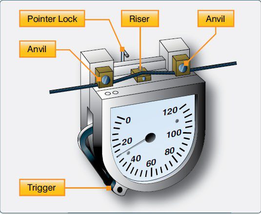
A tensiometer is used to measure the force required to produce a controlled deflection in the cable. Different instruments are designed for particular cable sizes, constructions and tension ranges.
Rigging Fixtures
Manufacturers may provide specialised fixtures, gauges or templates to measure control surface travel and confirm the required adjustment.
Tension Regulators
Some aircraft incorporate automatic cable tension regulators to compensate for differences in thermal expansion between the aircraft structure and steel control cables.
These systems use a spring and locking mechanism to maintain the required cable tension.
Turnbuckles and Locking Devices
Turnbuckle Assemblies
Turnbuckles are mechanical adjustment devices used to make small changes to cable length and tension.
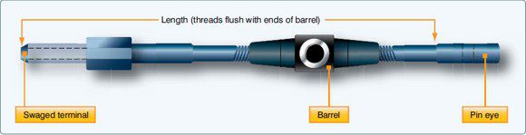
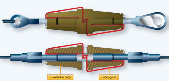
A typical turnbuckle consists of two threaded terminals and a central barrel.
One terminal has a right-hand thread and the other has a left-hand thread. Rotating the barrel allows both terminals to move inward or outward, adjusting the overall cable length.
Installation and Adjustment
When installing or adjusting turnbuckles, both terminals must be engaged correctly.
The source specifies that no more than three threads should remain exposed on either side of the barrel.
Once correctly adjusted, the turnbuckle must be secured using an approved safetying method.
Common methods include safety wire and specially designed locking clips.
Correct installation and security are essential to prevent unintended movement and loss of cable tension.
Cable Connectors and Spring-Back
Cable Connectors
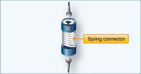
In addition to turnbuckles, some aircraft control systems incorporate cable connectors.
These fittings allow cable sections to be connected or disconnected when required.
The source illustrates a spring-type connector as one example of this arrangement.
Spring-Back
When a flight control cable system is correctly rigged, the flight control surface should reach its mechanical stop before the corresponding cockpit control reaches its own stop.
Spring-back describes the small amount of additional movement or force required for the cockpit control to reach its mechanical stop after the control surface has reached its travel limit.
Correct rigging and control stop adjustment are essential for achieving the aircraft manufacturer’s specified control movement.
Push Rods and Rod-End Attachments
Push Rods
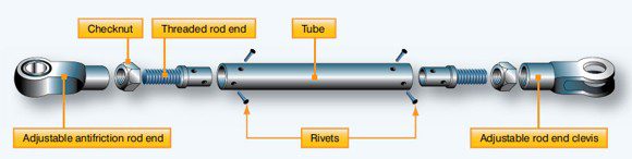
Push rods, also known as control rods, transmit push-and-pull movement through an aircraft’s flight control system.
They generally consist of a tubular body fitted with threaded rod ends and adjustable attachment fittings.
Depending on the design, adjustments may be possible at one or both ends.
Checknuts secure the rod-end fittings and help prevent unintended movement after adjustment.
Inspection and Installation
Unless specifically designed otherwise, control rods should remain straight and correctly aligned.
Installed rods must allow free movement throughout the required control range.
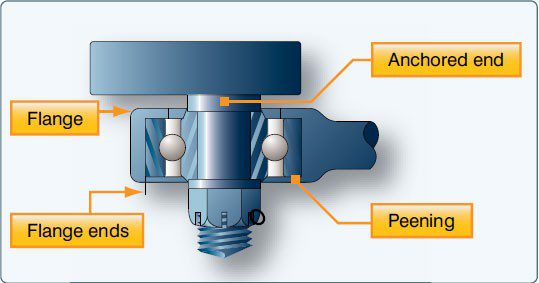
Special attention should be given to rod-end bearings and their attachment arrangements.
The source identifies a potential failure mode involving the peening used to retain ball races within rod ends.
Appropriate installation arrangements, including the positioning of rod-end flanges or suitable retaining washers, can help prevent complete disconnection if a bearing fails.
Torque Tubes and Cable Drums
Torque Tubes
Torque tubes are used in aircraft control systems where rotational or twisting movement must be transmitted between components.
They provide a mechanical connection that transfers angular movement to other control system components.
Depending on the aircraft design, torque tubes may operate in conjunction with control horns, quadrants and push-pull rods.
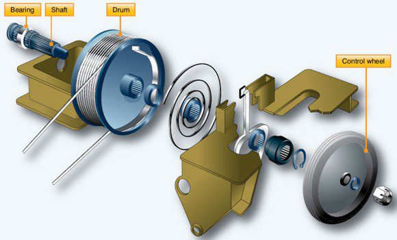
Cable Drums
Cable drums are commonly used in aircraft trim tab systems.
As the pilot rotates the trim control wheel, the cable drum winds or unwinds the associated control cables.
This movement is transferred through the trim system to adjust the position of the trim tab.
Correct installation and operation of these components are important to maintaining smooth and reliable control movement.
Closing note
Maintenance and Inspection Reminder
Aircraft control systems are critical to safe flight. Regular inspections, correct rigging, appropriate cable tension and properly secured fittings all contribute to reliable aircraft operation.
Aircraft owners and maintainers should always refer to the applicable aircraft manufacturer’s maintenance documentation and current regulatory requirements before undertaking maintenance or adjustment.
This article is based on technical material originally published in SportPilot in 2018. It is provided for general educational purposes and does not replace approved aircraft-specific maintenance instructions.